Elevation modeling: DTM, DSM, DEM explained
Choose the right elevation model for your projects.
If you've pulled elevation data from more than one provider, you've probably noticed that the terms Digital Elevation Model (DEM), Digital Terrain Model (DTM), and Digital Surface Model (DSM) aren't used consistently.
One provider calls their bare-earth grid a DEM. Another calls the same thing a DTM. A third uses DEM as an umbrella for everything. Many free datasets don't even flag which type they are.
It's easy to download a file, load it into CAD, and move forward, without realizing the surface you're working off isn't the one your design needs.
Using a DSM where a DTM is required, for instance, means your calculations are running off vegetation heights or rooftops rather than the ground, and that kind of error compounds. Volume estimates drift and drainage calculations skew.
By the time the problem finally surfaces in the model, you're looking at a rework and potentially expensive change orders.
Three terms, one umbrella
The short version: DTM = ground. DSM = ground plus everything on it. DEM = could be either, depending on the source.
Let’s start with the hierarchy.
The Digital Elevation Model (DEM) is the category, not a specific surface type. DTMs and DSMs are both types of DEM. In other words, DEM is any gridded dataset that stores a height value per cell, like a grid laid over the terrain, where each cell holds an elevation number. The confusion comes from how providers use the term. Many use "DEM" to mean bare-earth data specifically, so the same word ends up describing both the overall category and one of its members. When a provider labels something a DEM, check the metadata to confirm what surface it actually represents: bare earth, full surface including vegetation and buildings, or something in between.
The Digital Terrain Model (DTM) is bare-earth only. Vegetation, rooftops, structures, all removed. What's left is the ground surface, often enhanced with breaklines, ridges, valleys, and hydro features to preserve meaningful terrain shape. This matters in practice because those features preserve drainage paths and terrain behavior, something a simple grid alone can miss. It's the surface your design actually sits on.
The Digital Surface Model (DSM) captures the first surface the sensor hits. In a forest, that's the canopy. In a city, it’s rooftops and building facades. In an open field, it's indistinguishable from a DTM. The DSM preserves everything above ground, which makes it the right tool when those features are part of what you're designing around.
Why the distinction matters in practice
Choosing the wrong model isn't an edge case — it's a common source of real design errors.
Run grading calculations on a DSM for a forested site, and you're working off tree canopy, not ground elevation. Your cut/fill volumes will be off. Design a road corridor using a DSM in a built-up area, and your alignment is working against rooflines, not the actual terrain. The numbers look plausible in the model, but they don't reflect what your team will encounter on site.
The reverse also happens. Use a DTM for a telco line-of-sight analysis, and you've removed the very obstructions you need to account for. A signal path that looks clear on a DTM can be completely blocked in reality by a tree line or a building cluster.
The model you use should match what your analysis requires.
Which model to use, by project type
Ground-mount solar
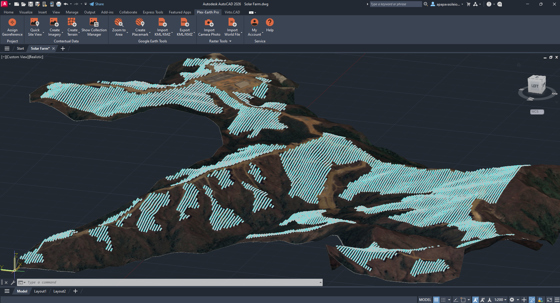
Solar Panels snapped onto Google Elevations*
Use a DTM. Slope analysis, drainage design, and earthwork volume calculations all depend on the bare ground surface. A DSM introduces canopy or structure heights that inflate terrain values and distort grading. On a vegetated site, you could be designing against treetops rather than the ground your panels will actually sit on.
Road and corridor design
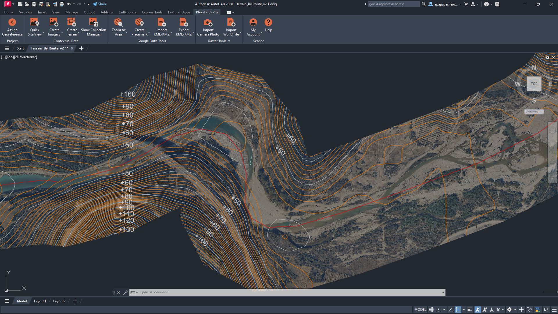
Terrain Contours with labels from Google Elevations* following a route
Use a DTM. Alignment, cross-sections, and cut/fill calculations are all ground-surface work. Consider a highway route across mixed terrain: even moderate tree cover or scattered structures in a DSM will shift your profile elevations and throw off earthwork estimates. The By Route option in Plex-Earth's Create Terrain tool lets you scope terrain extraction to a linear alignment rather than a bounding box, keeping the model lean and directly relevant to what you're designing.
Telco tower siting and line-of-sight
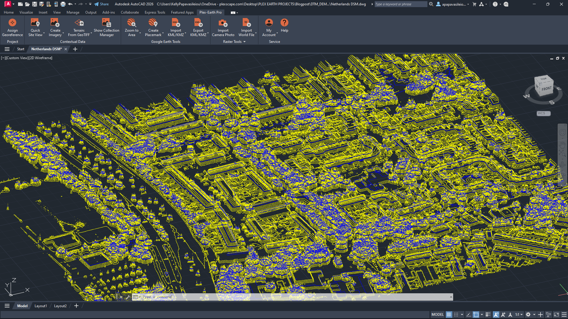
Terrain Contours from DSM from AHN (Actueel Hoogtebestand Nederland)
Use a DSM. Positioning transmission towers requires understanding not just the ground elevation, but everything that sits above it. Buildings, trees, and other structures are real signal obstructions, and a DTM strips them out entirely, giving you an unrealistically clear signal path. A path that reads as unobstructed on a DTM can be completely blocked at rooftop or canopy height in reality. For cable routing, a DTM handles the ground surface and earthwork calculations, but when above-ground obstructions affect your design decisions, the DSM is what gives you the full picture.
Environmental (Water/Wastewater)
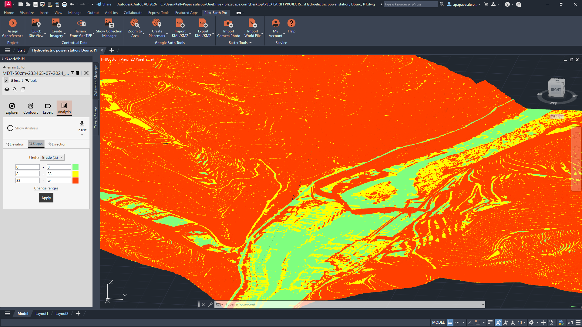
Terrain Slope Analysis from DTM from DGT (the Portuguese Territorial Directorate)
Use a DTM. Water flow, drainage basin delineation, and runoff analysis all depend on the bare ground surface. Buildings and vegetation don't redirect water, terrain does. This is one of the more accuracy-sensitive use cases: drainage modeling compounds errors downstream, so a DTM that accurately represents the ground is the right starting point, not a DSM that includes structures and canopy that water simply flows around.
Urban planning and drainage
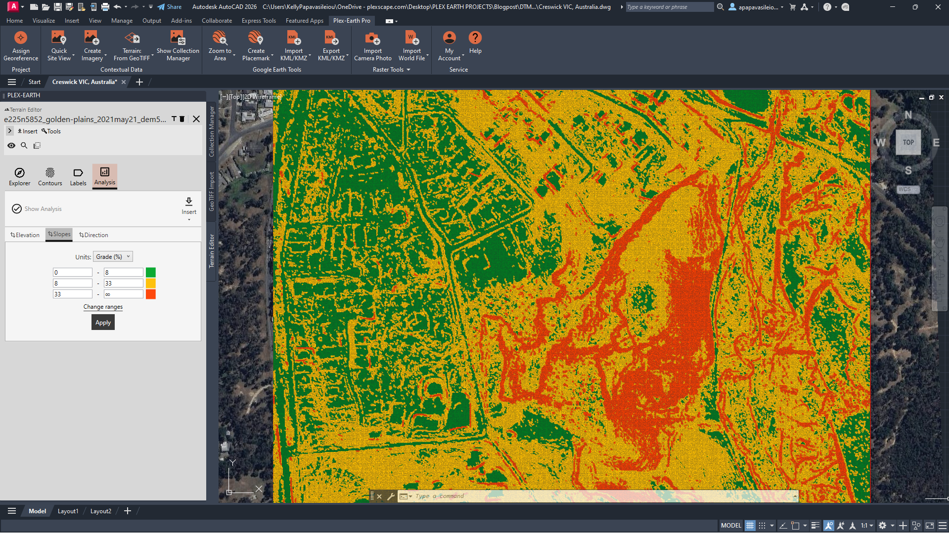
Description: Slope Analysis using © Commonwealth of Australia (Geoscience Australia) 2021 DEM
Here, you often need both at different stages. A DTM drives drainage analysis and infrastructure design. A DSM supports a 3D urban context, understanding how a proposed development interacts with the existing built environment, or how building massing affects shadow and airflow. Knowing which one you're working with at each phase prevents you from mixing inputs and drawing the wrong conclusions.
How terrain works in Plex-Earth
Plex-Earth provides DEMs directly through *Google Elevations, available on all plans with no additional setup. The Google Elevation API provides a DEM that, depending on the underlying data source, may approximate a terrain surface (DTM) in sparsely vegetated or rural areas, and closer to a full surface including buildings and vegetation (DSM) in urban or forested regions.
The data is derived from multiple sources and interpolated to fill gaps. This means fine terrain features, such as sharp ridges, narrow channels, and steep breaks, can get smoothed over in the output, and building or vegetation coverage is not consistent or reliable.
For early-stage analysis, Google Elevation data can serve as a terrain proxy, useful for getting a general understanding of the landscape, but it should thus not be treated as a high-precision terrain model for engineering-grade applications.
For DEMS, DTMs, and DSMs with greater regional detail, free country-specific datasets from national mapping agencies and open geospatial portals are available as GeoTIFFs and load directly into CAD via the Terrain from GeoTIFF command.
When free sources don't have the resolution or coverage your project requires, higher-quality DTMs and DSMs from premium providers are available through the same workflow. Contact us for more information.
As simple as that, no GIS tools, no external platforms, no format conversions, just bring terrain directly into your drawing.
Getting terrain into CAD with Plex-Earth
Create Terrain from Google Elevations
Produces a DEM, and the process goes as follows:
Georeference your drawing first, required before terrain creation
Ribbon → Contextual Data → Create Terrain (or run PXV_TERRAIN)
Define your area: draw directly in CAD, paste coordinates, or copy a polygon from Google Earth
Choose your output: contour polylines, TIN mesh, elevation points, or a Civil 3D surface
For custom resolution, open PXV_TERRAIN_PROVIDERS → click the gear icon → untick automatic mesh calculation
This is the right path for solar feasibility, corridor scoping, rural infrastructure, and any early-stage work where a reliable DEM is all you need. Full guide: Create Terrain
Create Terrain from GeoTIFF
DTM or DSM, depending on your source file, which means this is also how you bring in free country-specific elevation data from national mapping agencies and open geospatial portals, as well as premium provider datasets.
Prepare a GeoTIFF with valid elevation data
Ribbon → Contextual Data → Create Terrain dropdown → Terrain from GeoTIFF
Select your file; the GeoTIFF editor opens in Collection Manager
Adjust resolution (higher resolution = more points, longer processing)
Select a sub-area if you don't need the full extent
Choose output: TIN mesh, contour polylines, elevation points, Civil 3D surface, or dynamic terrain model
If no coordinate system is detected, Plex-Earth applies a custom georeference automatically
This workflow handles telco line-of-sight, drainage analysis, and any complex site where Google Elevations resolution isn't enough, whether your source is a free national dataset or a premium provider. Full guide: Create Terrain from GeoTIFF
The decision in brief
Getting terrain right at the start of a project costs almost nothing. Getting it wrong means volume estimates built on vegetation heights, drainage calculations off a surface that includes rooftops, and errors that compound the further the project progresses. For earthworks specifically, using a DSM instead of a DTM is a well-documented source of inflated cut/fill estimates, with the difference between models being significant enough to affect budgets on larger sites.
DTM when you need the ground surface. DSM when surface features are part of what you're designing around. DEM from Google Elevations when you need a reliable starting point fast.
Most teams are already managing enough context switching: GIS platforms, satellite portals, CAD, and whatever format the data provider decided to use that week. Plex-Earth keeps all of it inside AutoCAD and Civil 3D. The right terrain model, from the right source, georeferenced and ready, without leaving your drawing environment.
Start a free trial and bring terrain into your drawing in minutes.